Login
You are currently not logged in! Enter your authentication credentials below to log in. You need to have cookies enabled to log in.
Spline fitting
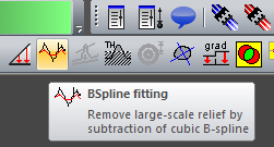
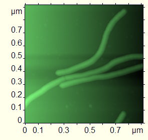
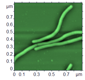
Often the surface pattern and distortions that may occur because of the non-linearity of the piezoceramic manipulator as a whole distort the image in such a way that the subtraction of the surface of the second order does not make it vivid enough. FemtoScan software can form bilinear cubic splines for surfaces and subtract splines from surfaces. To subtract a spline please select the Spline Fitting command from the Mathematics menu or click on the button
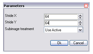
To form a spline the surface is divided into rectangles which sides are indicated in the dialog box that will appear after the command is called up in parameters Step along X and Step along Y. In every rectangle, the average surface height is calculated and the spline is formed based on the central points of the rectangles, where the earlier defined average heights are considered to be the value along axis Z.
For the best performance of this filter, it is better to select such sizes of the rectangles’ sides that would appear in the image as an integer.
Just like in the case of the Fitting, you can select the value for the Subimage processing field:
- Separate - for every image that the file contains, the average surface defined by the smallest square method for the specific image is calculated;
- Use active - the surface is calculated for the active image and is subtracted from all the images;


